The post A Closer Look: Concepts to Ponder on appeared first on International Robotics Championship.
]]>Law of the Lever
A lever is one of the simple machines that has laid a foundation on engineering. It consists of two basic components: a beam fixed at a point called the fulcrum. The lever rotates on a point on itself, providing what we call leverage.
The Law of the Lever can be interpreted as such:
“As the lever rotates around the fulcrum, points farther from this pivot move faster than points closer to the pivot. Therefore, a force applied to a point farther from the pivot must be less than the force located at a point closer in, because power is the product of force and velocity (Uicker, Pennock and Shigley, 2010).”

Meaning to say, given two points a and b where a has a greater distance from the fulcrum, the input force applied in point a would be amplified, thereby increasing the output force expedited in point b. If the reverse was true, and the distance between the point of input force (point a) is shorter than the point of output force (point b), then the lever reduces the magnitude of the force.
For key takeaways, the further from the fulcrum a force is applied, then the less effort is needed to move the lever.
Rotation Angle
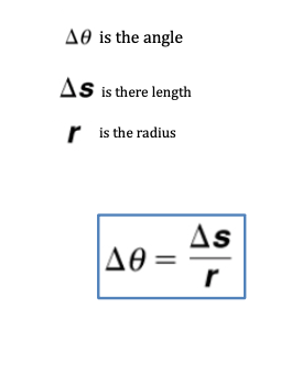
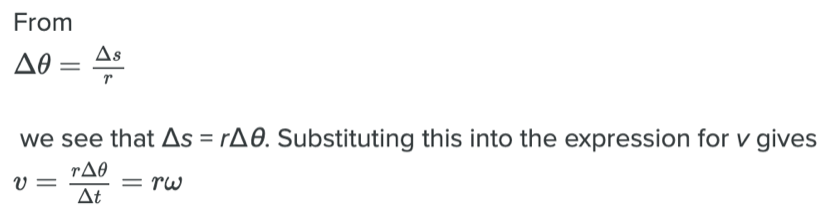
When objects rotate about some axis—for example, when the compact disc rotates about its center—each point in the object follows a circular arc. Consider a line from the center of the CD to its edge. Each pit used to record sound along this line moves through the same angle in the same amount of time. The rotation angle is the amount of rotation and is analogous to linear distance. We define the rotation angle Δθ to be the ratio of the arc length to the radius of curvature:
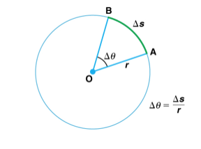
The arc length Δs is the distance traveled along a circular path. Note that r is the radius of curvature of the circular path.
We know that for one complete revolution, the arc length is the circumference of a circle of radius r. The circumference of a circle is 2πr. Thus for one complete revolution, the rotation angle is
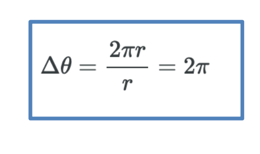
The result is the basis for defining the units used to measure rotation angles, Δθ to be radians (rad), defined so that 2π rad = 1 revolution.
Angular Velocity
How fast is an object rotating? We define angular velocity ω as the rate of change of an angle. In symbols, this is
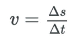
where an angular rotation Δθ takes place in a time Δt. The greater the rotation angle in a given amount of time, the greater the angular velocity. The units for angular velocity are radians per second (rad/s).
Angular velocity ω is analogous to linear velocity v. To get the precise relationship between angular and linear velocity, we again consider a pit on the rotating CD. This pit moves an arc length in a time.
Rotational Inertia
Rotational inertia is the property of an object to counter the direction of its spin in relation to a rotational axis. This is a fundamental concept in physics that is used in problems involving angular momentum and how the distribution of mass correlates to the rotational motion or velocity of a spinning object.
Rotational inertia is dependent on (1) the mass and (2) the distribution of the mass relative to the axis of rotation. Moreover, it is also important to account the momentum of the object. A mass that moves farther from the center or point of rotation is harder to change rotational velocity than a mass that is closer to the axis of rotation.
In essence, the heavier the mass of the rotating object, the harder it is to change the rotational velocity and direction of its spin. Keep in mind these handy lessens as they can help you better understand the concepts behind the challenge. We hope this helps, and good luck to all IRC participants!
References:
– Uicker, John; Pennock, Gordon; Shigley, Joseph (2010). Theory of Machines and Mechanisms (4th ed.). Oxford University Press, USA. ISBN 978-0-19-537123-9.
– Lumen Learning , Physics
The post A Closer Look: Concepts to Ponder on appeared first on International Robotics Championship.
]]>The post Weighing the Right Choice of Matter appeared first on International Robotics Championship.
]]>Have you ever realized how much you have grown from when you were little? Right now, you are probably thrice your size from when you were a toddler. While it is more apparent to notice the weight of things in a large scale, do you know even the smallest bit of matter, the atom, also carries weight?
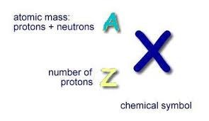
Atomic mass is measured by the sum of protons and neutrons in the nucleus of a certain atom. Because electrons weigh so little, they usually do not contribute to the atom’s mass. As we know, different atoms with different properties are classified as elements. Each of the 118 elements listed in the modern periodic table has their own corresponding atomic masses.
It must be known, however, the term Atomic Mass should not be confused with Atomic Weight. Atomic weight is the relative atomic mass of each element. Think of it as the ratio of the average mass of an element by also considering its isotopes. An isotope is a species of a certain atom that differs by the number of neutrons. For instance, do you know carbon has Though sometimes the Atomic mass and Atomic weight are used interchangeably just as seen in the examples below, it is important to recognize their difference.

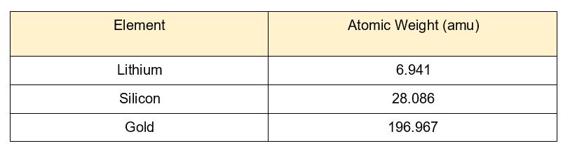
Atomic weight is measured in atomic mass units (amu), also called daltons. Here is a list of some elements with their atomic weights. (Tip: these are hints for the 4th stage so read them carefully!)
All of the known elements to man have their atomic weights not only identified, but also tactically arranged in the periodic table. Looking at the periodic table, you could have noticed that the atomic weight increases as atomic number increases. From left to right, the atomic weight increases. The same increasing trend is seen from top to bottom.

Since it is unpractical for scientists to count the number of particles in a given reaction, chemists will opt to weigh each of the atoms to scale their quantity. The atomic weight is a fundamental property of matter because it can greatly predict the behavior, reaction and tendencies of the atom which could help scientists arrive to quantifiable conclusions.
Sources:
https://www.remm.nlm.gov/atomicshorthand.htm
https://socratic.org/chemistry
https://www.thoughtco.com/color-periodic-table-with-atomic-masses-608859
The post Weighing the Right Choice of Matter appeared first on International Robotics Championship.
]]>The post How to Install Third Party Blocks (like RGB block) In EV3 Mindstorms appeared first on International Robotics Championship.
]]>- If you want to install the classic Mindcub3r block, download ColorSensorRGBzip-v1.00.zip to your computer.
- If you want to install the enhanced RGB block from ODFL, download this block on your computer.
On a computer running Windows, find the file in Windows Explorer, click with the right mouse button and select Extract all…
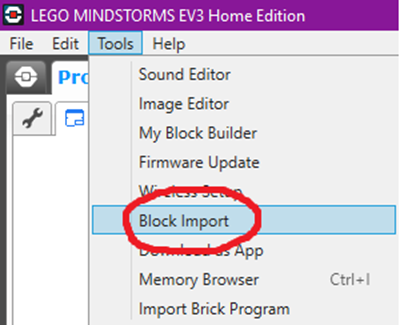
- In the Block Import and Export dialog, select Browse.
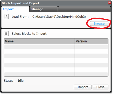
- Find the file, which has .ev3b extension on your computer and Open it.

- Select the .ev3b file from Select Blocks to Import and then select Import.

- To complete the installation, close the dialogs and exit from LEGO MINDSTORMS EV3 software.
Source:
How to build MindCub3r for LEGO MINDSTORMS EV3: http://mindcuber.com/mindcub3r/mindcub3r.html
The post How to Install Third Party Blocks (like RGB block) In EV3 Mindstorms appeared first on International Robotics Championship.
]]>The post How to Use Sensors In RGB Mode appeared first on International Robotics Championship.
]]>The original EV3 color sensor supports reflected light, ambient light and color mode, but this does not meet our needs. David Gilday, who made mindcuber, created the EV3 Color RGB mode in the early days, which greatly improved the EV3 Color Sensor.
Original Digital Flipped Lab (OFDL) have added other functions, including the RGB comparison mode and the raw value mode.
You can download the block from here: https://github.com/a10036gt/EV3-ColorRGBEnhanced-Block/releases/

How it works
The block has 3 different modes which will help you use sensors in enhanced way:
Measure – RGB color
This mode returns the Red, Green and Blue components of the RGB color.
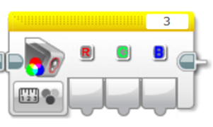
Compare – RGB color
This mode is a variant of RGB mode, which allows you to change the input value to achieve the judgment effect, as shown above: 20 is Error Amount, R, G, B are 170, 160, 120, respectively.
The object reads Red to 150-190, Green at 140-180, and Blue at 100-140. When the three are established, the Boolean value is finally output.
The interval is determined by Error Amount, which is what you input. The RGB value +-Error is the judgment condition.

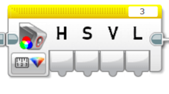
HSVL Mode
This mode allow you reading the HSVL value of EV3 Color sensor (convert from RGB).
Citation:
ODFL Original Digital Flipped Lab
https://ofdl.tw/en/ev3-hacking/ev3-color-sensor-adv-block/Ver 1.6:
.Add HSVL Mode.
.Remove Raw value mode (merge to EV3-AdvEV3Col-Block)
Download
Download Link (GitHub):
Author:OFDL HSU、T2H Robotics
Ver:1.6
The post How to Use Sensors In RGB Mode appeared first on International Robotics Championship.
]]>The post How to Solve Complex Tasks appeared first on International Robotics Championship.
]]>What is the Goal Breakdown Structure?
If you search on the internet, you will find various definitions, some complicated, some simple to understand. In case of robotics missions as you are given in our competition, you can translate it into breaking the big task into multiple, simpler tasks, which are or are not related between each other.
This kind of practical thinking is something that us, humans, do all the time. For example, when we go to school, we need to do some simple tasks in the process:
- get dressed:
- check weather first;
- get proper clothing;
- fill our schoolbag with whatever we need and equip it;
- make sure we close our house door;
- take the bus:
- find a seat on the bus;
- check we have everything we need to proceed;
- get to class:
- make sure you know to which class you are heading;
- put your stuff in the locker;
- keep only the necessary stuff for the class.
As you can see, there are little goals you need to achieve and have certain subgoals which will finish the main goal. But every each one of them is simple, easy to understand and has little instructions in the process.
Now that you understood this, let’s go back to robotics  . We will use the mission from stage 3 as an example.
How to breakdown a robotics mission
Understand needed principles
First of all, you need to look at the whole mission and identify what principles apply for it. Let’s have a look at it.
You can see certain elements which are obvious: we have black lines on white background, white lines on black background and maybe some orange lines on black background. Then, there are some blocks which needs to be pushed and some rotating devices on the other side of the table.
So, the principles involved are:
- classic line follower (following black line);
- inverted line follower (following white line);
- color line follower (following orange line);
- push regulated objects (you can push the orange blocks and also the rotating devices).
These are also the simple tasks the robot has to perform.
As you can see, these are basic functions, which need some skills of programming and designing the robot, but it is not something new or unique. I am sure you have done this a couple of times before .
Ok, you understood this part. What now? Well, we need to design the robot which can carry out these simple tasks.
Designing the robot
Robot design is very important as many of the simple tasks will be solved by the construction itself. Think how you will push the object so that the robot should just move forward, without the need of having additional claw or mechanisms. The simpler the design, the more effective!
Then, you need to think what programming algorithms you know and how that influences the design. For example, you know how to implement the classic line follower with only one sensor? Good for you! Now where do you put that one sensor so that the robot can move quick and correct?
You need to ask yourself all these questions before starting the design. Maybe you will not get it right at first, because after testing you will see you will need some more stuff. That’s alright, it will surely happen. But, if you are giving it some thoughts before the first iteration, maybe you will not need to make so many of them afterwards.
After you feel the design is ready, you need to create some basic functions so that you will simplify how you will right the code. In most cases, the functions are custom blocks.
Creating basic custom blocks / functions for the robot
This will certainly help you simplify your code. Let’s say you need to create a line follower block. You should create one which will have some parameters, like speed or turn correction. Why? Because in some cases you will want to move faster, in others you will want to move more precise.
For the given example, you can see that if you implement a classic line follower algorithm, which stops whenever intersects a black line, the robot will travel from the start all the way up to the table. Simple, right?
So, the main program will just have one block for line follower instead of 10 blocks for just one path to be followed. It will be much more quicker to go through the code when you will want to make adjustments and will save you lots of time.
Also, if there is a problem in the line follower algorithm, you will need to correct it in just one place instead of many others.
Conclusion
This is just a basic method to solve complex missions for every competition, not just this one. Of course, you should not exaggerate and think of every action as a goal, but little by little you should start to gain progress.
Remember this little thing: whatever you need to solve was created by a human, so there is a solution to it. And most probably, he created the mission in the same way you want to solve it: step by step .
The post How to Solve Complex Tasks appeared first on International Robotics Championship.
]]>The post Line follower concepts appeared first on International Robotics Championship.
]]>- The simple line follower program is the most basic of the four types, it also wiggles a lot because of the sharp turns, so it is not smooth.
- Make sure to calibrate your censors, since the programs use the EV3 Colour Sensor in Light Sensor.
- And so, the second type would be the smooth line follower, where it is almost exactly like the simple, however the turns are not as sharp, this will result in issues on sharp curves.
- The third type is the 3-stage follower, this is best used for straight lines, and nested switches are needed
- The final type is the proportional follower, which makes proportional turns. This type works well on straight and curved lines.
- The pseudocode of this follower is: first, reset the rotation sensor, compute the errors and determine the distance from the line, establish the correction amount and adjust the scaling factor, then use the correction value to adjust the robot’s line following.
The post Line follower concepts appeared first on International Robotics Championship.
]]>The post Programming #101: The Line Follower Principle appeared first on International Robotics Championship.
]]>Switch Line Follower
The Switch Line Folllower requires the use of loops and switches and wiggles a lot due to sharp turns.

The switch block is used to represent the if/else logic of the algorithm. This is where the decision to do one action or the other action is done. In the case of the line follower, this is where the robot will know if it will turn left or right.
The loop block is used to tell the robot how many times the action will be performed. For the line follower, the switch block is inside the loop block and the robot will perform the color reading according to the number of times indicated in the loop block.

The pseudocode for this kind of follower is as follows:
- Take a new light sensor reading.
- Compare the reading to the set threshold value. To set the robot just at the edge of the line, the threshold value should be set to 50.
- If the condition is true, turn the motor to the right.
- If the condition is false, turn the motor to the left.
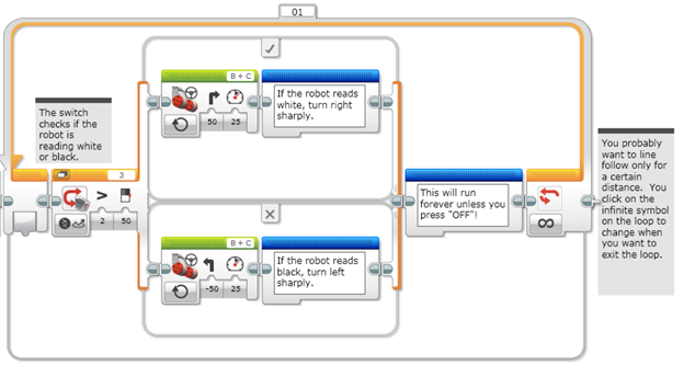
This is a sample program for a switch line follower. The sensor will check if it senses black or white. If it reads white (> 50), the robot will turn right sharply. If it reads black (< 50), the robot will turn left sharply. This action is placed inside a loop and the programmer can dictate how long the robot should perform this action.
Proportional Line Follower
The other line follower to be discussed is the Proportional Line Follower. It is more sophisticated than the switch line follower because it uses Math Blocks and Data Wires. With the use of these blocks, the robot can take readings and do corrections based on the readings.

The Math block is used to perform mathematical operations such as addition, subtraction, multiplication and division.
The data wire is used to take an output data from one block and used it as input data in another block.

The pseudocode for the Proportional Line Follower can look like this:
- Reset the Rotation sensor (Only required for line following for a total distance)
- Take a new light sensor reading.
- Compute the error. Distance from line = Light sensor reading – Target reading
- Scale the error to determine a correction amount. Adjust the scaling factor to make the robot follow the line smoothly.
- Use the correction value (from Step 4) to adjust the robot’s turn towards the line.
This is a sample program:

- Step 1 is to reset the rotation sensor.
- Step 2 is when the color sensor will take a light reading and input it into the Math block as variable a.
- Step 3 is when the Math block will compute the error which is a – b. Then the output will be inputted to the next Math block which is Step 4.
- In Step 4, the Math block will multiply the error by a scaling factor or a Constant of Proportionality. This scaling factor is based on the robot design and can be usually determined thru trial and error. The correction will then be inputted to the move steering block to adjust the robot’s turn towards the line.
- Steps 2 – 5 are inside the Loop block and can be performed according to what the programmer needs.
These two Line Followers are the most commonly used. Aside from these two, what other kind of line follower do you know or have you created by yourself?
Sources:
https://ev3lessons.com/en/ProgrammingLessons/advanced/LineFollower.pdf
https://ev3lessons.com/en/ProgrammingLessons/advanced/ProportionalLineFollower.pdf
The post Programming #101: The Line Follower Principle appeared first on International Robotics Championship.
]]>The post Calculating Velocity of Lego EV3 Large Motor in a Projectile Motion appeared first on International Robotics Championship.
]]>The EV3 Large Servo Motor is a powerful motor that uses tacho feedback for precise control to within one degree of accuracy.
By using the built-in rotation sensor, the intelligent motor can be made to align with other motors on the robot so that it can drive in a straight line at the same speed. It can also be used to give an accurate reading for experiments.
The motor case design also makes it easy to assemble gear trains.

Specifications:
- Tacho feedback to one degree of accuracy;
- 160-170 rpm;
- Running torque of 20 N/cm (approximately 30 oz/in.);
- Stall torque of 40 N/cm (approximately 60 oz/in.);
- Auto-ID is built into the EV3 Software.
Combining knowledge from projectile and getting the velocity of the rotating body such as EV3 large motor can lessen your trial and error with your robot.
Using the formula of V = 2 .rN or
DN
- V – velocity of the body rotating m/s
- r – radius of rotation
- D – diameter of rotation
- N – no. of rotation/revolution per minute
Sample
A 50g Blue ball will be thrown in a plain field with an angle of 45 degrees. Using the large motor with a 170rpm (max) how far will it go if the throwing arm has a length of 100mm.
Using the formula above in getting the initial velocity that will be applied to the Ball
V = 2 (3.14)*(0.1m)(170rev/min)
V = 106.8 m/min
V= 1.78 m/s
Using this V as the initial velocity of the object in projectile motion, we can get the maximum distance it can reach using the formula
R = V2 x sin2(Ø) / g
R = (1.78m/s)2 x sin2(45)/9.81m/s2
R = 0.507m
Note that If we decrease the value of rotation of the large motor, we also decrease the peripheral velocity of the object and shorten the distance it will travel.
The post Calculating Velocity of Lego EV3 Large Motor in a Projectile Motion appeared first on International Robotics Championship.
]]>The post What is A Catapult and How Does It Work? appeared first on International Robotics Championship.
]]>A catapult is a ballistic device used to launch a projectile a great distance without the aid of gunpowder or other propellants.
A catapult uses the sudden release of stored potential energy to propel its payload.

Parts of a Catapult
- Bucket – a container use to hold the payload prior to release;
- Payload – the object that will be discharge in projectile motion;
- Arm – holds the Bucket that has a pivot connection at the base;
- Base and Frame – Supports the Catapult’s weight and action;
- Rope – stores potential energy by stretching or winding up while it is attached directly or indirectly to the arm;
- Restraining Rope – it serves as the trigger of the catapult once release;
- Counterweight – used in other type of catapult. Stores potential energy by setting it in a higher elevation and drop it once the restraining rope is released.
Energies involved in the catapult’s mechanism
There are three primary energy storage mechanism used in a catapult.
- Tension – is built by stretching the rope up to the maximum limit. When it is stretched, the potential energy stores in the rope, parallel to the direction of how it is stretched.
- Torsion -is built in the pivot point of the arm. the more you twist the rope, the greater energy you stored tangent to the center of rotation.
- Gravity – counterweight is one type of storing the potential energy by pulling a heavy object against the gravitational force.
Once the Payload is released in the Catapult, it will create a projectile motion towards the direction it is positioned.
Effect of Velocity in a Projectile Motion
Velocity is the distance travelled of an object over time. In a projectile motion, it affects the distance travelled of an object. The higher the velocity, the farther it can reach at the same angle.
To show you the effect, in image 2, we have a cannonball weighing 20kg that is shot at an angle of 45 degrees.


Effect of Angle in a Projectile Motion
Angle affects how far and how high the object will go in a projectile motion.
Using the simplified formula: R = (Vo2sin2Ø)/g
- R – Range
- Vo – Initial Velocity of the Object
- Ø – Angle of discharge in a projectile motion
- G – Gravitational force
We can compute for the maximum distance traveled.
Here are the samples images with same object and initial velocity but differs in the angle.

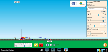

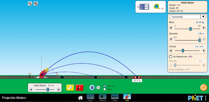
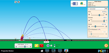

Do you see the changes in distance and height travelled by the cannonball at different angles?
At 45 Degrees, the vertical and horizontal forces are equal giving the cannonball the farthest distance it can reach at a given velocity and gravitational force.
While at 90 degrees, the cannonball can attain the maximum elevation it can reach at a same velocity and gravitational force
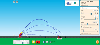
Effect of Gravity in a Projectile Motion
Every planet has its own gravitational pull. Here on earth, our gravitational pull is 9.807m/s2, while on the moon it is 1.62m/s2. This force is pulling the object towards the center of the planet. In a projectile motion, it affects the time an object will hit the ground, the distance it will travel, and the maximum height it can achieve.
In image No. 9, it shows changing the value of gravity in a 20kg cannonball that fires at 20m/s velocity at 45-degree angle.


The lower the gravitational pull, the farther the object can travel at a given instance.
You may also check https://phet.colorado.edu/sims/html/projectile-motion/latest/projectile-motion_en.html for you to explore more about projectile motion by varying the gravitational force and including Air resistance of the object.
The post What is A Catapult and How Does It Work? appeared first on International Robotics Championship.
]]>The post Physics #101: The Forces Implied in Kicking appeared first on International Robotics Championship.
]]>So what is the science, or more specifically the physics, behind soccer? You will find that forces is one of the principles that you have probably learned from school by now. But just to recap:
- Force – a push or a pull, acting on an object as a result of its interaction with another object. It is a vector quantity which means that it has both magnitude and direction. There are two broad categories of forces: contact force and action-at-a-distance force.
Contact force is the type that result when two interacting objects are perceived to be physically contacting with each other. Examples are the following: Frictional force, Tensional force, Normal force, Air resistance force and Applied forces.
- Frictional force – The force exerted by a surface as an object moves across it or makes an effort to move across it.
- Tensional force – the force that is transmitted through a string, rope, cable or wire when it is pulled tight by forces acting from opposite ends.
- Normal force – the support force exerted upon an object that is in contact with another stable object
- Air resistance force – a special type of frictional force that acts upon objects as they travel through the air.
- Applied force – force that is applied to an object by a person or another object.
Action-at-a-distance force, on the other hand, are those types of forces that result even when the two interacting objects are not in physical contact with each other, yet are able to exert a push or pull despite their physical separation. Examples are Gravitational force, Electrical force and Magnetic force.
- Gravitational force – the force with which the earth, moon, or other massively large object attracts another object towards itself.
- Electrical force – the repulsive or attractive interaction between any two charged bodies
- Magnetic force – attraction or repulsion that arises between electrically charged particles because of their motion.
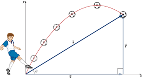
Now, let’s see what forces are applied on soccer ball.


When the soccer ball is at rest, the only forces acting upon it are the gravitational force and normal force which are equal and opposite in direction. Since the forces are balanced, the object remains at rest.
Following the Newton’s First Law of Motion, the Law of Inertia, the object will stay at rest or uniform in motion unless acted upon by an unbalanced force. In other words, to make the ball move initially, an applied force which is the kick should be applied. How hard the person kicks the ball will dictate the initial velocity and the angle of the trajectory (curved path).
Now, all this is explained in the situation in which we have gravity. In the first mission though, things are a bit different: the gravitational force is missing! Complete the first mission of Stage 1 and, based on your experience, try to write down how does an object behave when kicked in an environment where there is no gravity.
Source: https://www.physicsclassroom.com
The post Physics #101: The Forces Implied in Kicking appeared first on International Robotics Championship.
]]>